Cable Ladder Support Span Calculation

Structural Steel Beam Sizing Chart In 2020 Structural Steel Beams Steel Beams Beams
Http Www Sourceiex Com Catalogs Chapter 2014 20cable 20support 20systems Pdf

Small House Floor Joist Spacing Floor Joist Span Table Floor Framing Floor Framing Flooring House Flooring

Cable Trays Nema Classifications Unistrut Service Co

Cable Support Systems Design And Installation Ee Publishers

Cable Tray Raceway Fill And Load Calculations Electrical Engineering 123
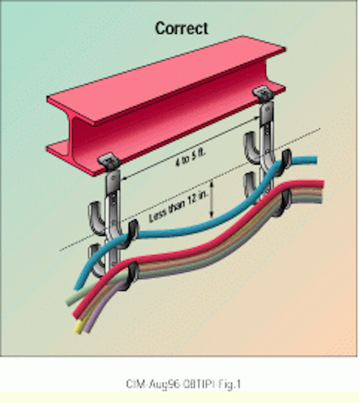
To ensure adequate support accessories should be supported locally.
Cable ladder support span calculation.

Maximum Vertical Acceleration For Different Depth To Span Ratios And Download Table

Image Result For Trex Stair Treads Trex Stairs Stairs Deck Stairs

Untitled
Https Www Nextgenscaffold Com Wp Content Uploads 2017 08 Il1 Tech Manual 82917 Pdf

Marina Ogurcova Dizajn Ofisov Home Office Layouts Home Office Design Furniture Design

Use This Deck Stair Calculator To Determine The Riser Height Angle And Total Run For Your Stair Stringers Input The Building A Deck Deck Builders Deck Design

Joint Reinforcement Less Is More Masonry Magazine
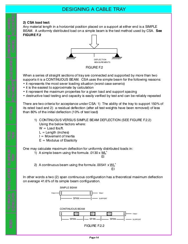
Designing A Cable Tray

Arc 110 And Cot 109 Roof Truss Design Roof Trusses Roof Repair

Used Pallet Rack Pallet Racking Warehouse Shelving Warehouse Rack Storage Racking

Sxt3 Premium 100 Stainless Steel 5 8 Key Receiver Lock 2 3 4 Span Key The Same As Spare Tire Cable Locks Stainless Steel Receiver Hitch Lock
Tibmsxuj68orem

Best Practice Guide To Cable Ladder And Cable Tray Systems Pdf Free Download
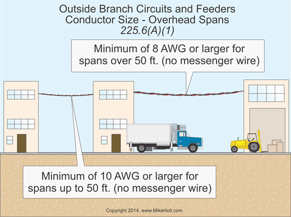
Nec Rules On Outside Branch Circuits And Feeders Ec M

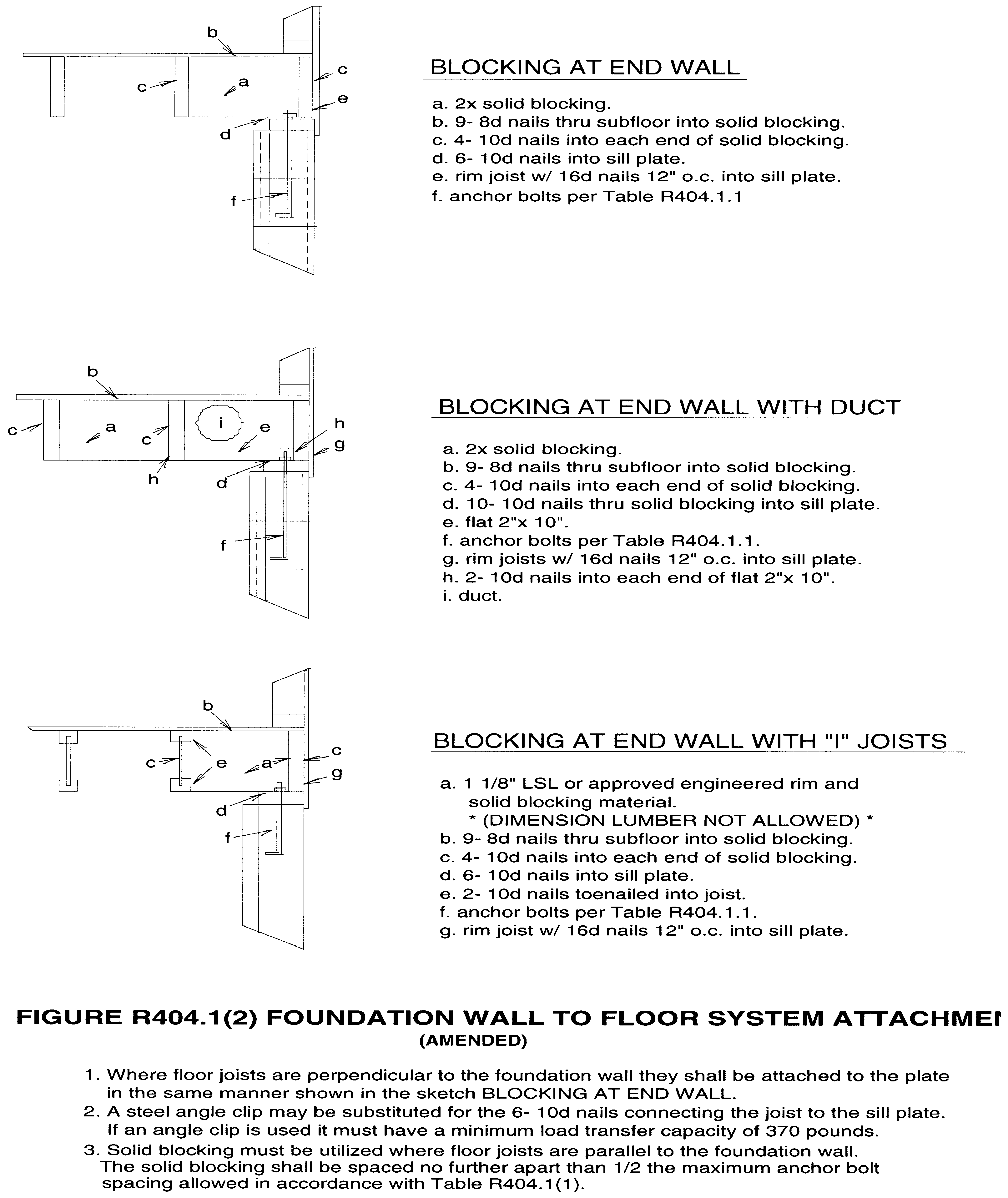
Chapter 23 Wood 2017 Fbc Building 6 Sup Th Sup Edition Upcodes
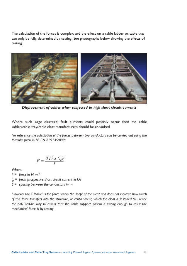
Beama Best Practice Guide To Cable Ladder Cable Tray Systems

Turn Your Wasted Garage Space Into Additional Storage Area Custom Storage Loft In Garage In 2020 Pegboard Garage Garage Storage Shelves Garage Storage Organization

How To Build A Chop Saw Station Chop Saw Drill Press Stand Saw
Https Encrypted Tbn0 Gstatic Com Images Q Tbn 3aand9gcsmxdv2pm4r0pfnffjfq45ftbqzaflcphzwu0yr3wtnpcnbqfna Usqp Cau

How To Build Deck Around An Above Ground Pool Google Search Pool Deck Plans Building A Deck Deck Steps

Pin En Equipamiento Car And Truck

April 2 Sean School Bus Camper Bus Conversion School Bus Conversion

Load Tables Bar Grating Brown Campbell
The Nec And Optical Fiber Cable And Raceway Rules Ec M

Pin By Candice Ellis On For The Kids Zip Line Backyard Ziplining Backyard
Http Www Parks Ca Gov Pages 1324 Files Chapter 2016 20 20trail 20bridges Final 04 04 19 Pdf

Lawriter Oac

Chapter 31 Vents 2015 Michigan Residential Code Upcodes
Use Wide Base J Hooks To Support Category 5 Cable Cabling Installation Maintenance

Meet Sam Raymond The Owner Adventure Company Upper Peninsula Michigan Michigan Waterfalls
Https Www Metelmex Com Wp Content Uploads 2016 05 Steel Bar Grating Catalog Metelmex Pdf
Yv0w T2cjozeam
Http Www Co Douglas Or Us Building Pdfs Residentialcodesummary Pdf

Conductor Tension An Overview Sciencedirect Topics
Http Www Kirbyinternational Com Userfiles Broucher 72206 Kirbytechnicalhandbook Pdf
Https Library E Abb Com Public A23c0c6d7a3247e7aa8d1cd74f4ad6d5 16412 1810 Abb 9akk106713a6719 Abb 20cable 20management 20solutions 20ct R1 Pdf
Https Ww2 Eagle Org Content Dam Eagle Rules And Guides Current Offshore 291 Gn Specificationsjunctionbox And Cable Tray For Offshore Application 2018 Junction Box And Cable Tray Gn E Feb18 Pdf
Https Www Emcstandards Co Uk Files Reo Guide To Fixed Installation Best Practice Pdf
Https Allstarce Com Wp Content Uploads 2016 12 2017 Nec Code Ch 2 Article 215 225 3 Pdf
Https Www Cookcountyil Gov Sites Default Files 14 5599 Electrical Code 1 Pdf
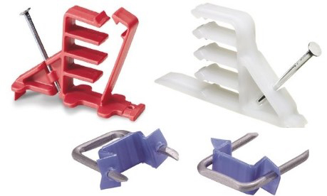
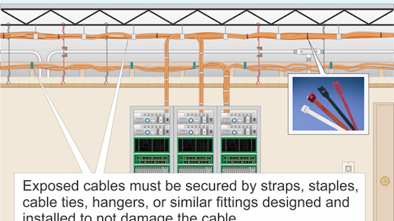
Securing And Supporting Cables And Raceways Jade Learning
Https Www Teldor Com Files Php Actions Show Id 7655
Http Www Iaea Org Inis Collection Nclcollectionstore Public 26 001 26001059 Pdf
Https Encrypted Tbn0 Gstatic Com Images Q Tbn 3aand9gcrv0p7vfiu1w4jziq2zlqxzo8bfpoxughzuzwzgczml3qvjw9 5 Usqp Cau
Source : pinterest.com
